Description
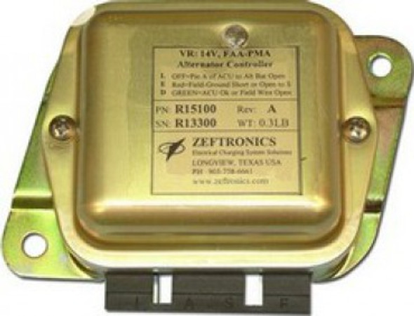
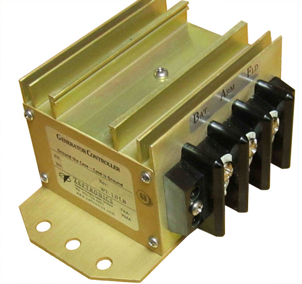
28V 50A Twin Engine Generator Controller: Generator System Voltage Regulator
What’s included:
- Installation Drawing
- Warranty Card
- Product Eligibility Catalog (PEC)
- Troubleshooting Notes
- Instructions For Continued Airworthiness Maintenance (ICA)
Product Features:
Voltage Regulation, IC Sense Referenced
The Voltage Regulator (VR) controls the Generator’s field to keep the aircraft electrical system voltage at a specific level. This controller has a “Type A” regulator which excites the field of the alternator by providing controlled ground to one side of the field (F), with the other side internally connected to the armature.
Electronic Controlled Generator Build-up / Automatic field flashing
The Generator Build-up function allows the rotating generator to build-up its output from a low residual voltage to the system’s voltage regulation point.
Electronics Field Controller/Switching
The VR electronics switch turns the field current on/off so fast (several times a second) that the output voltage of the generator stays at the VR set point. When the generator’s output voltage exceeds the VR set point, the switch opens, current flow stops, and the generator’s output decreases.
Current Limit, IC Sensed & Controlled
The Current Limiter (CL) controls the maximum output current the generator can produce. It turn off the field excitation when the output current exceed the CL set point (determined by the generator’s current rating). It allows normal field excitation when the generator output is below the GCU CL set point.
Reverse Current Protection
The Reverse Current (RC) Protection circuit blocks the battery current from going back to the generator. It allows current to flow only from the generator to the battery and system.
GCU induced Over Voltage (OV) Protected
The GCU’s design will cause the field current path (between the field and ground) to open if the field control device becomes internally ground shorted. This means that the GCU will not induce Over-Voltage (OV) problem into the system. The GCU does not protect the system against externally induced OV faults.
Trouble-Shooting Lights on Unit
The on-unit system Trouble-Shooting Lights, TSL, identify how the system is operating and, helps with system testing and troubleshooting. The lights indicate Generator Off/On-line (GO, GREEN), Voltage Regulation (VR, GREEN), Current Limit (CL, RED), and Parallel (EQ, or Load sharing, GREEN).
Other Features:
- Footprint Compatible to Delco-Remy’s VR
- Increase Regulator Life
- Not Temperature Sensitive
- Prevents Regulator cycling at low RPM
- Eliminate Regulator Noise
- More Precise Current Limit
- Prevents Battery Current Flowing to the Generator
- GCU will not cause OV fault in the system
- Reduce Trouble-Shooting Time
Product Reviews
Shipping & Returns
Shipping (USA)
Shipping is available via UPS or USPS and most items ship within 24 hours if the order is placed between Sunday and Thursday. Orders placed after 11am EST for USPS and after 2pm EST for UPS my not ship the same day. If your order comes in prior to that Monday through Friday, we try to get it out same day. All USPS shipments are picked up by Noon Monday through Friday. All UPS shipments are picked up by 3pm EST (sometimes earlier) Monday through Friday.
Any date estimates on shipping are provided by the shipping companies and do not include processing time, please be advised of that when making your shipping decisions. Their estimates do not factor in weekends, holidays, or processing time.
If you are local to SkySupplyUSA (New Castle, PA - about an hour north of Pittsburgh and an hour south-east of Cleveland), please feel free to stop in during our business hours Monday - Friday 8:30am - 5pm EST. If you know exactly what item you're looking for, give us a call and we'll have your items pulled at the front counter!
We can also ship with your FedEx or UPS account number, please call us for more information on those options.
Please also note that the shipping rates for all items we sell are weight-based. To reflect the policies of the shipping companies we use, all weights will be rounded up to the next full pound. We realize this sometimes causes inflated shipping rates when ordering a large quantity of items, so if you feel that the estimator is giving you an outrageous shipping quote, feel free to reach out and we can double check.
Expedited Shipping (UPS Next Day, 2nd Day, or 3 Day)
Orders placed after 2 PM EST will be shipped the next business day.
UPS does not pick up on Saturday or Sunday, so all weekend orders will ship on Monday.
International Shipping
We can ship to almost any destination in the world. International customers must understand that all packages are shipped after a (3) day Review period and must clear customs in your country. The amount of time to do so varies from country to country and we have no control of the package during that time.
Customs, Duties, and Taxes (International)
You are responsible for assuring that the product can be lawfully imported to the destination country. When ordering from SkySupplyUSA, the recipient is the importer of record and must comply with all laws and regulations of the destination country. Orders that are shipped to countries outside of the United States may be subject to import taxes, customs duties and fees levied by the destination country. The recipient of an international shipment may be subject to such import taxes, customs duties and fees, which are levied once a shipment reaches your country. Additional charges for customs clearance must be borne by the recipient; we have no control over these charges and cannot predict what they may be. Customs policies vary widely from country to country; you should contact your local customs office for further information. When customs clearance procedures are required, it can cause delays beyond our original delivery estimates.
Returns Policy
You must call or email for an RMA number. No refunds on unauthorized returns.
We offer a 30 day return period. Returned items must be in "brand new" condition and in its undamaged original packaging to be eligible for return. Spark plugs must be in their sealed plastic sleeves. Opened sleeved spark plugs are not returnable. There will be a 20% - 40% restocking fee on all non-defective products. The restocking fee varies from product to product. Special order items are not returnable.
You must pay the return shipping costs. If the return is a result of our error (you received an incorrect or defective item, etc.), we will refund it once the item has been returned in new condition and the issue is verified. Please note that computer software that has been opened or activated cannot be returned. Defective software will be replaced with the same product as purchased. All shipping charges will be paid by the buyer.
Refunds cannot be guaranteed for non-trackable shipping.
You should expect to receive your refund within four weeks of giving your package to the return shipper, however, in many cases you will receive a refund more quickly. This time period includes the transit time for us to receive your return from the shipper (5 to 10 business days), the time it takes us to process your return once we receive it (3 to 5 business days), and the time it takes your bank to process our refund request (5 to 10 business days).
If your item includes a manufacturers return policy that differs from SkySupplyUSA policies, you will need to contact them directly to resolve your issue.


